Professional Cost effective. Wire colors for individual and common connections on fluorescent ballasts will vary depending on ballast type, bran and the number of lamps. Find the Newest Product.
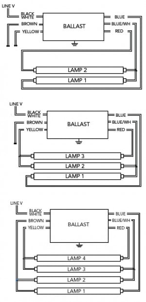
Assortment of fluorescent ballast wiring diagram. A wiring diagram is a streamlined standard pictorial representation of an electric circuit. Ballasts have a wiring diagram to show how they connect to the lampholders. There are four basic types of fluorescent ballasts : Instant start electronic ballasts use a high starting voltage (about 6volts) to start very quickly (less than seconds). Collection of fluorescent emergency ballast wiring diagram.
Watch as Total Bulk Lighting provides an overview of the fluorescent Tballast and what all those wires mean. It actually is a lot simpler than then you think! The wiring process of fluorescent tube lamp/light with Ballast , Starter is quite easy and simple.

In most cases when we buy a fluorescent light it comes in a complete set with all wire connected. If you want do it yourself (DIY), you can buy all the parts individually. And you can complete all connection of the fluorescent light/lamp with the help of this wiring circuit diagram. Snip the old fluorescent ballast wiring several inches from the end of the fluorescent ballast with a side-cutting pliers or wire snips. Cut all the wires connected to the fluorescent light ballast.
Ballast Wiring Diagram Series ballasts can only be wired in series according to the diagram on the ballast. Parallel ballasts can only. Wiring Diagram of Single Tube Light Installation with Electronic Ballast How to Install a Single TubeLight with Electromagnetic Ballast As no starter is used in case of electronic ballast application, wiring diagram is little bit changed. Improve Your Business ROI - Get A Better Deal On Magnetic Ballast. Save Big On Home Lighting!
In concept replacing a fluorescent lamp ballast or transformer is pretty simple; what can be intimidating is the plethora of wiring diagrams on the new ballast , none of which matches exactly the wiring diagram on the original unit. Fluorescent Fixture Wiring Diagrams The following wiring diagrams are typical of fluorescent fixtures using iron ballasts. The old ballast housing did not fit over the new ballast , and I got frustrated and decided to try the LED suggestion. Wiring up the LEDs to bypass the ballast entirely was easy and seemed like a good idea. If you are replacing a Tballast , the wiring of the old ballast should be the same as that on the new ballast.
If the old ballast was a different type, the wiring in the fixture, including the. Follow the colore-coded wiring diagram was the recommendation, yet after connecting all like colors on the new ballast to the fixture, all I got was a delaye dim light at the base of each fluorescent bulb. I suspect the wiring is not as simple as described. So, how to wire the new ballast to my fixture so it works? The classic fluorescent lamp design, which has fallen mostly by the wayside, used a special starter switch mechanism to light up the tube.
You can see how this system works in the diagram below. No power will be run to the other end ( the diagram below is for single end LED Tballast bypass lamps) When wiring TLED bulbs, the reason this requires non-shunted sockets is that the LED lamp is single end-powered. THE EMERGENCY BALLAST WIRING GUIDE This Document has been customized to contain a wide library of individual dia- grams for various installation applications.
If a diagram cannot be found within this selection, consult Customer Service.
No comments:
Post a Comment
Note: only a member of this blog may post a comment.